Retrofit Leachate Well Spacing and Yields
Many old landfill sites were constructed without basal leachate drainage systems and in more recent landfills some of these systems have failed. Leachate level control in these sites requires installation of retrofit leachate extraction wells through the waste. The cost to drill these wells is not insignificant and unless they are constructed carefully and robustly they often need replacing within a few years. During operation, yields from leachate wells can be affected by biofouling and gas as well as the intended reduction in leachate levels.
Based on work published in Canada by Rowe and Nadarah (1996) (Estimating leachate drawdown due to pumping wells in landfills, Canadian Geotechnical Journal, 33, pp1-10, 1996), Nick developed an Excel spreadsheet approach to allow well spacings and yields to be estimated for leachate wells completed in different depths of waste. The effects of clogging were also examined. The approach was also used to evaluate the effect of surcharging on the likely number of wells required to achieve compliance.
Estimating Leachate Well Spacing and Yields

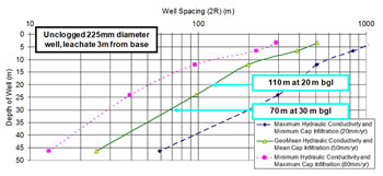
Well Spacing Diagram, click the image to enlarge*

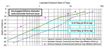
Leachate Extraction Rate diagram, click the image to enlarge*
These charts illustrate the calculated reduction in well spacings and yields with increasing depth of waste.
The changes with depth are due to an anticipated decrease in the hydraulic conductivity of the waste as published by Powrie and Beaven in 1999.
(Powrie W., Beaven R. P., (1999). Hydraulic properties of household waste and their implications for fluid flow in landfills. Proceedings of the Institution of Civil Engineers (Geotechnical Engineering), 137 (4), 235-247.)
The first diagram highlights that the wells need to be closer together where the waste (and compliance level) is deeper due to the decrease in the waste's hydraulic conductivity with depth.
The second diagram highlights that well yields are calculated to be lower where the waste is thicker due to the decrease in the hydraulic conductivity of waste with depth.
* These images have been taken from slides 21 and 22 of an Entec UK Ltd presentation published on the Geological Society's website (See Reference #14 on Downloads page).
As a follow on to the theoretical spreadsheet work, Nick designed a programme of leachate well testing, undertaken by WRG, to provide data on well yields and drawdown data that were interpreted to provide a check of the waste hydraulic conductivities used in the spreadsheet calculations. The measured data and Nick’s predictions matched well.

